Bend Angle Tolerance Sheet Metal
Sheet Metal Bending Tolerances
Bend Tolerances Sheetmetal Me

Machined Sheet Metals Angle Misumi Misumi Misumi
Bend Allowance Sheetmetal Me
Sheet Metal Forming
Outside Setback Sheetmetal Me

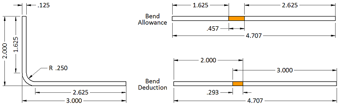
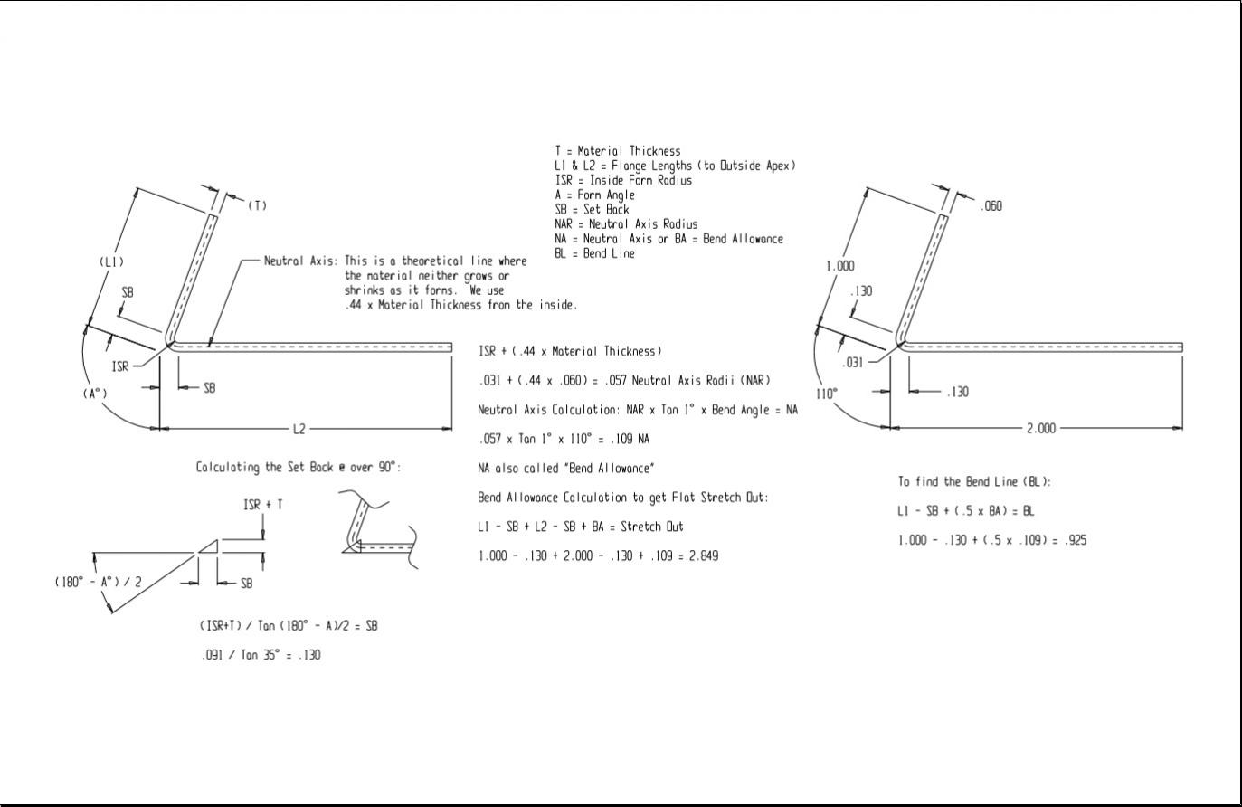
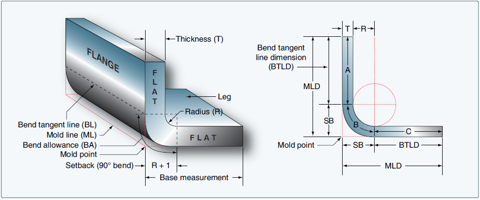
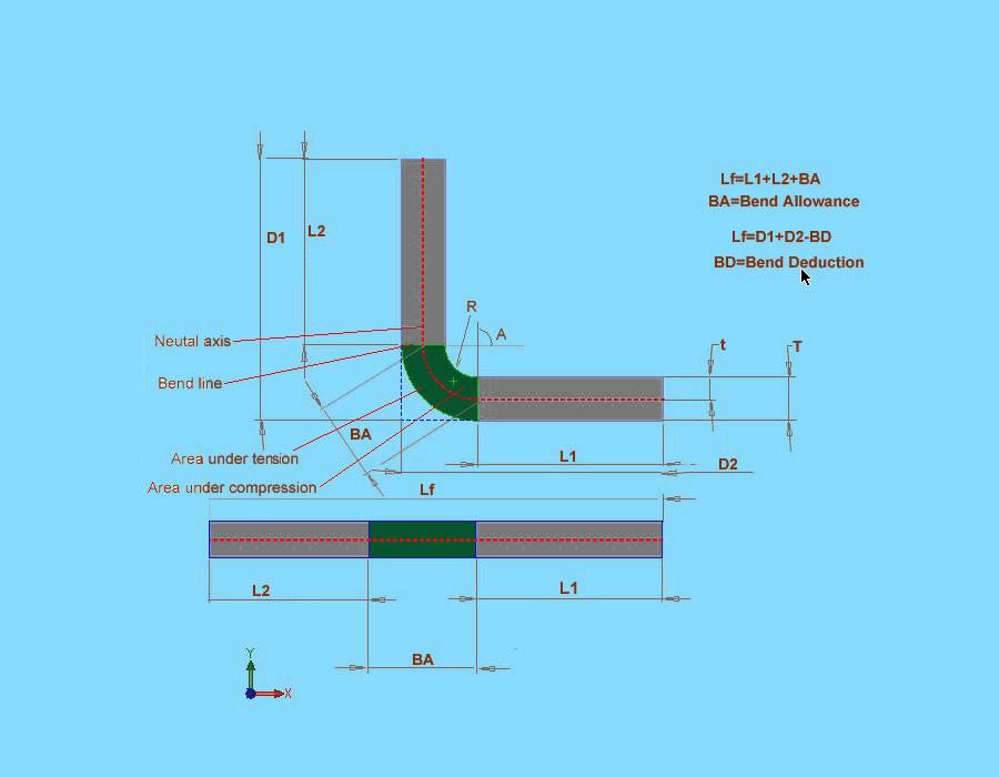
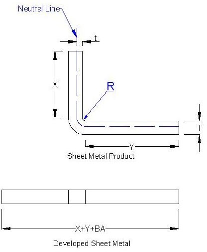
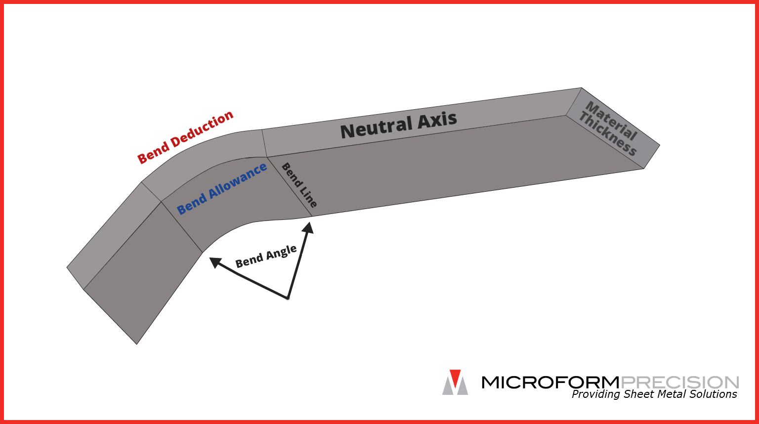
The bend allowance and bend deduction are two measures that relate the bent length of a piece of sheet metal to the flat length.
Bend angle tolerance sheet metal.

Tolerance Image Sheet Metal Fabrication Metal Fabrication Welding And Fabrication
Practical Machinist Largest Manufacturing Technology Forum On The Web
Aircraft Sheet Metal Layout And Forming Aircraft Systems
Solidworks Tutorial Sheet Metal 2012 What Does Bend Allowance Mean Youtube

Sheet Metal Design Guide Geomiq

Sheet Metal Tolerance Chart In Mm In 2020 Sheet Metal Sheet Metal Gauge Stainless Steel Sheet

Sheet Metal Bend Radius Unfold Table Autodesk Community Inventor
Sheet Metal Design Guide Calculate Bending Allowance Accurately Bright Hub Engineering

Mechanical Design Tutorial Sheetmetal Design

Sheet Metal Bend Allowance Calculator

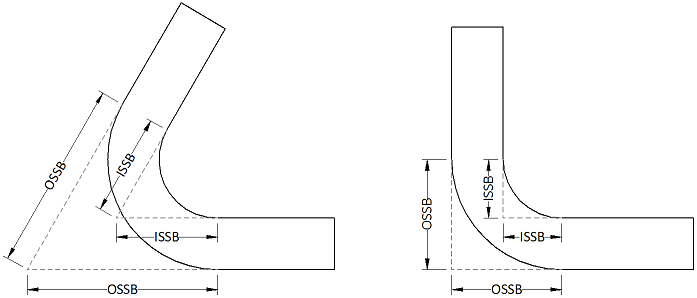
L Shaped Sheet Metal Mounts Symmetrically Placed Misumi Misumi Misumi

Sheet Metal Fabrication Guide Tenere Inc

L Shaped Angle Mounts Dimensions Configurable Misumi Misumi Misumi
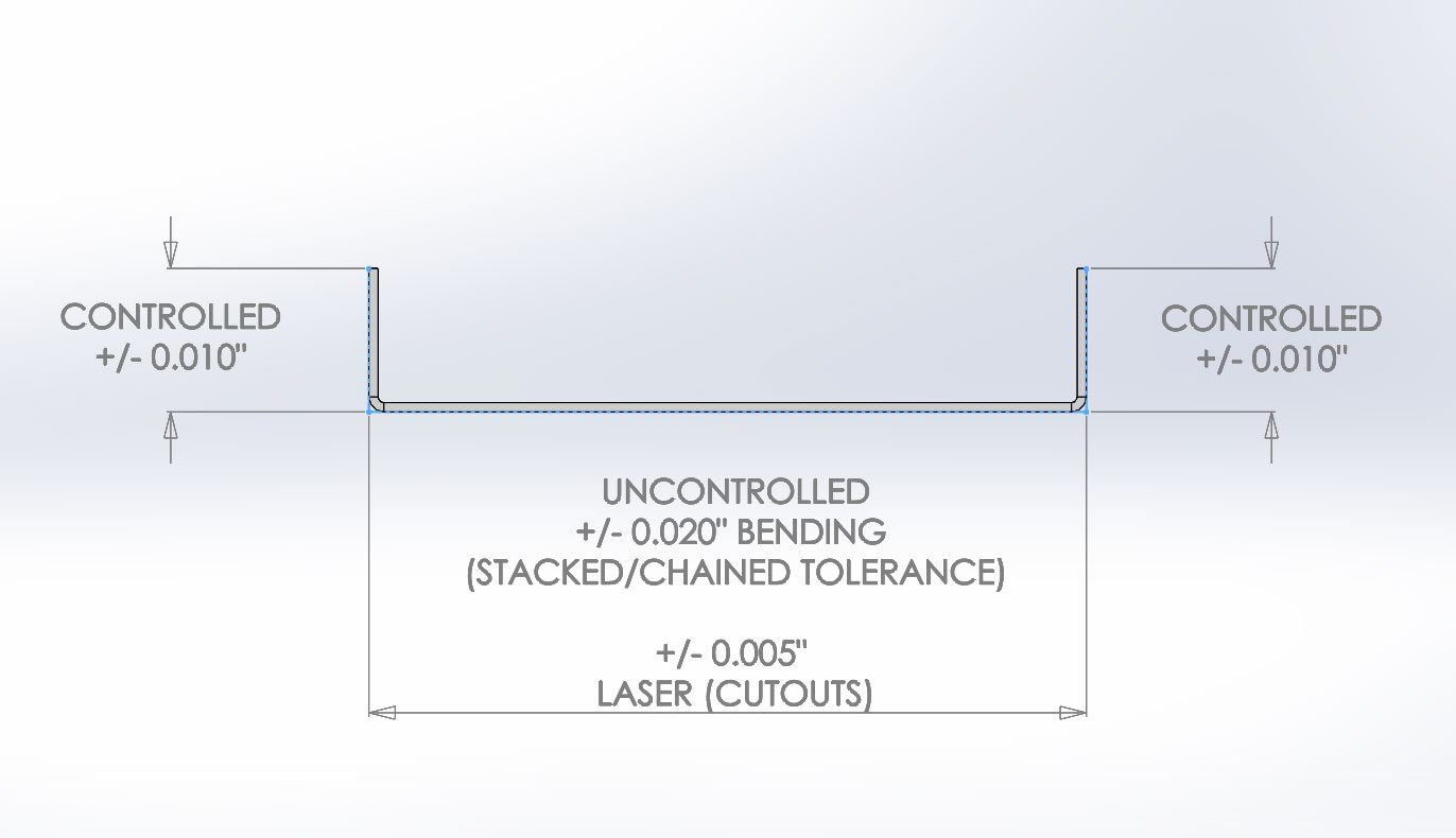
What Sheet Metal Shops Wish You Knew Reasonable Tolerances Grain Direction And The Base Flange

R D Update Press Brake Bending

Design Considerations For Sheet Metal Parts

Sheet Metal Mounts For Sensors Motors Or Cylinders Convex Bend Misumi Misumi Misumi

Solidworks Mbd Sheet Metal Support Is New For Solidworks 2019
Https Encrypted Tbn0 Gstatic Com Images Q Tbn 3aand9gcqeso Lunplefah9ymmybpmkjurgyyfalio4tc2se5mvkx0ra2r Usqp Cau
Tom S Techniques Reference Reference Reference Chart Techniques
Following Dfm Guidelines For Working With Sheet Metal Machine Design

Sheet Metal Mounts For Sensors Z Bend Misumi Misumi Misumi
Online Bend Deduction Calculator Microform Precision

Sheet Metal Mounts For Sensors Z Bend Misumi Misumi Misumi
Source : pinterest.com
